1999 Ford Ka Heater Control Valve Repair
At the time of writing this document the car I use and own is a 1999
Ford Ka. It is a lovely wee car that offers an excellent blend of
manueverability, cabin space and acceptable power to give you a good
small city car. I've owned this one since buying it as an ex-demo item
from the car dealer and it has by and large given me good service.
However much as I love the car I will never buy a Ford again.
This isn't because the car design is bad at all. Indeed I love this
car and the little design touches that show someone thought about the
use of the car carefully. No I won't buy a Ford again because while the
design is pretty sound Ford decided to cheap out on the materials used.
To give you an idea in this cars nine and a half year life it has had :-
- At the three year mark the car rear exhaust muffler rusts at the
welds and fall off. Three days after Ford personel certified,
serviced and warranted the car.
- Four year mark sub surface rust spots appear. As well an
incorrectly fitted body panel rubs on the passenger side front roof
column causing it to rust. Have to have a long argument with Ford to
get it attended to under the five year rust cover warranty.
- Five year mark the steel tyre rims rust sufficiently to fail the
warrant of fitness check. Somehow this occurs inside six months,
according to Ford, as they swear blind no rust was showing on the
previous WOF check. (After three years of life a car shifts from
yearly to six monthly WOF checks, up to this point all servicing and
checks have been carried about by the Ford dealership I bought the
car from - at considerable expense compared to other servicers.)
Despite admitting in the Small Claims Court case that not only was it
unusual to have all four rims rust to this point and that the rust
occured on a part of the car that the car owner cannot be expected to
clean, namely the inside of the rims Ford refuses to cover the rims
as simple defective manufacturing. Instead they argue that this is
environmental rust caused by where I live. Of course having lived
here almost forty years now we have had a series of cars none of
which have had rust issues to speak of.
The irony is that when factoring in the staff time Ford NZ spent
defending themselves in the Smalls Claims Court alone, let alone the
amount of time letter writing and answering phone calls to get to
this point, they have spent more than what the rims were worth at
customer pricing. Clearly Ford believes less in customer satisfaction
than a blind adherence to the principle of never admiting any fault.
One curiousity is that the spare tyre rim which is stored slung under
the car and thus exposed to the same conditions has some mild surface
rust but is still servicable at nine years of age. Also the
replacement rims, exposed now for four and a half years to the same
conditions, show no sign of rust. Environmental, my arse.
- Eight year mark and the front right brake return piston rusts
into a fixed position. This causes the brakes to be constantly partly
on and as such wears the brake pads and rotors out on both front
wheels.
- At nine years the oil sump rusts through starting a fairly serious
oil leak issue.
- At nine and a half years the exhaust pipe between the engine and
first muffler is showing signs of pitting through thanks to rust. I
am advised it likely needs replacing soon.
My suspicion is that this car has been either shipped on deck or left on
the wharf for an extended period to engender a lot of these problems. It
seems to be unusually suffering from rust issues - even my previous car,
a 1972 Ford Escort had less problems than this newer one has. What
really rips my rationbook is that Ford itself acknowledges these flaws
in succesive models of the car but refuses to deal with them for the
people who bought the early model. Later Ka's come with an aluminium oil
sump and alloy wheels as standard precisely because these are both well
known defects with the car.
Speaking of defects this leads me to the point of this page. Recently
my heater packed in so that I was only getting cold air supplied in the
car. Given that it is summer verging on autumn at the time this isn't a
huge issue till you have a wet humid day where you are trying to keep
the front windscreen from fogging. At which point not having heat to dry
the incoming air out becomes very much an issue - a dangerous issue that
I needed to fix. At the same time the fan speed control had also
partially died with the lowest fan speed not working. So thanks to the
wonders of the internet and some parts ordering I decided to try and fix
these myself.
Now the fan speed is relatively easy - a resistor pack mounted in the
passenger footwell space provides the speed step down. This is secured
by one screw and is comfortably reachable from inside the car. So that
got replaced in the carpack of the parts supplier. One problem down, one
to go. The research I'd done on the heating issue pointed firmly to the
heater control valve. It further indicated that this was a pretty simple
part to replace but while moderately detailed textual descriptions exist
no images of how to do this are out there. I figure I'd both have a go
at doing this and at documenting it a bit to give others a more visual
path to follow.
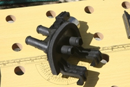 So here is the part in its new glory the hooks face forward and grasp
the engine bulkhead between the engine bay and the passenger
compartment. Fundmentally it is a simply device - the solenoid on the
side accepts a varying voltage and as such varies how much pressue it
exerts on a value. That regulates the speed of water flow and
consequently how much hot water is fed from the engine to warm the air.
This is another fairly widely acknowledged minor design fault with the
Ka's. These solenoids tend to fail after a few years mostly from
weathering damage as while this unit is buried beneath plastic facia it
isn't in a sealed space and water does tend to pass through. Certainly
the solenoid I pulled out was fairly pitted and looked like it had
jammed. It also hadn't aged well - the plastic had become quite brittle.
Something that surprised me a little as usually plastic ages from
ultraviolet exposure breaking the plastic molecules up. Here sunlight
wasn't an issue so I have to assume, seeing as it was the hot water feed
side that was the most feeble, that it is thermal stress occuring.
Now I should make something very clear here. I am not a mechanic and
this is my first go at a major bit of car servicing. I certainly have
tinkered with repairing the radio system (Ford chose heavy inflexible
wire for the door pass through leads to the speakers, this means they
will snap as the action of opening and closing the door wears them.) but
actually tinkering with an engine component like this is something new
to me. This I think is the other reason for putting this up - if I can
do this succesfully then anyone with a mild bit of mechanical aptitude
should have the confidence to give it a whirl as well.
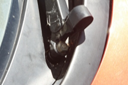 Step One - remove the windscreen wipers. You need to remove the
plastic facia that is underneath them so off they come. Hidden under
that end covering is the locking nut which holds the wipers on along
with a washer to help the nut not move. It is worth noting that when
putting these wipers back on you don't want to over tension them - just
tight enough to be firm will do. Too tight and you can cause the
windscreen motor to strain.
I must apologise for the blurriness of the shot here. Because I was
using my good digital camera and I was getting oil, grease and other
gluck over my hands while working on this (and I had already been
looking in the engine bay to decide if I could move the water expansion
tank or not, so very dirty hands) I wasn't operating the camera well. In
particular I was trusting the shots were coming out okay instead of
double checking them on the LCD screen. Silly me I know but even with
the blurr this shot is clear enough to see where the locking nut lurks.
So it wasn't a total disaster.
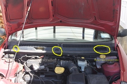 Step Two - with the wipers off begin to remove the plastic facia.
This is held on by a set of six screws covered with plastic lugs just
underneath the windscreen but on the outside of the car. With a sharp
knife pop the lugs out and unscrew them. Now you need to open the
bonnet. Three more fixing screws are at the bottom of the top piece of
plastic facia and in recessed pockets. These three need to come out as
well. They attach the top plastic pieces to a plastic divider in the
engine bay. I've marked them in the photograph with yellow circles to
make it clear where they hide. Once they are out you should be able to
lift the top plastic piece out. Be aware that the windscreen washer
nozzles are connected by a hose that needs to be unplugged before you
can fully pull the plastic off. This hose has a handy disconnection
point near the nozzle end you can use. The top piece splits into two
parts and can be put to one side. On the top of the plastic divider is
some split rubber hosing acting as a vibration damper for the bonnet (I
think). This needs to be pulled off as well.
You most likely will find a lot of debris and gluck in here. Spiders
it seems just love the grill in the facia and set up home in here. On
top of that dirt and other random crap will have collected underneath
the facia. I took the opportunity of having the cover off to clean the
area a bit. Not vital but makes working in this space more pleasant. A
bucket with some water and a damp cloth do the job nicely.
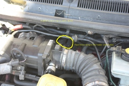 Step Three - sighting the beast's lair. Technically this occured
before step two back there but what the hey. Before I got too keen in
pulling things apart, and possibly not getting them back together again,
I wanted to see where the valve lived and how tricky it was going to be
to get to it. I've circled the first sign I had by looking for the
feeder hoses that connect to the valve assembley from the engine. As you
can see it is right at the back in the engine bay in the middle of the
bulkhead. Not the easiest of locations to get to if you happen to be
short. It is worth pointing out here that this location means you really
do need a fully cold engine before doing this work. You are going to
have to squeeze your hands around the top of the engine block to access
behind the plastic divider. Obvious point I know but getting burns on
your hands isn't funny so I'll be a little obvious.
I also marked out the rubber hose I talked about in step two just to
be clear.
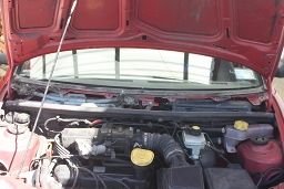 Step 4 - work on the plastic divider. With the top plastic facia
and rubber damping hose off you can now work on freeing up the plastic
divider itself. This is fixed by six screws. Two on either side of the
engine bay under the bonnet hinges. Nice and easy to get at. One in the
centre connecting to a metal linking arm that connects to the car body
just under the windscreen. Also nice and easy to get to. One on the top
of the plastic divider panel just to side of its central split. Finally
two hidden down behind the engine slightly to the right of the feeder
hoses going to the heater control valve. These are nasty to get at and
require winkling your hand in over the top of the engine block but
underneath what I think is the vacuum feeder tube. Patience and a
careful approach is advised. Be aware that you will likely drop these
screws - fortunately directly beneath them is pretty muuch clear space
so they will fall out of the engine bay to the ground. It isn't so bad
removing them but fitting them back in is perhaps the trickiest part of
the entire job. You want as long a phillips head screwdriver as you can
get your hands on for this. The longer the better.
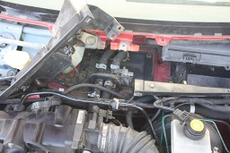 With all the screws out the plastic divider also splits in two and can
be manipulated a fair bit. Now a chunk of the wiring loom runs along the
top of the divider and is clipped in place. You can open these clips and
release the wiring which then lets you bend one half of the plastic
divider out of the way. Ford procedure is to unclip everything off the
divider and remove it entirely. That seemed like entirely too much work
for my liking. So as you can see in the image I just bent it up enough
to keep it out of my way without having to do much more.
Congratulations! The bulk of the work is now out of the way and the
valve itself is now exposed and ready to be replaced.
Step Six - replace the valve. Now the valve assembly is held
in place by its hooks and the hoses attached to it. Begin to remove the
hoses by squeezing the metal ring clamps together to loosen them and
move them up the hose away from the valve assembly. I found an
adjustable grip tool worked well for this - simply set the appropriate
grip width and you can adjust these clamps fairly easily. To prevent mix
ups I disconnected one hose at a time and immediately attached it to the
same port on the replacement valve. The hooks on the valve itself and
the solenoid give you an easy visual orientation and surprisingly little
water comes out. The valve itself is mounted slightly above the engine
and I think the heater matrix inside the car is below it too - so most
of the water is perfectly happy to stay where it is.
An important point to note, you are messing with the cars cooling
system. Internal combustion engines run hot and do rely heavily on the
cooling system to keep them from self destructing. The cooling system
also runs at about 1.5 to 2 times atmospheric pressure so when putting
the hoses on the new valve ensure they are firmly seated and that the
metal ring clamp is over the bulge at the end of the valve fitting point
and it clamps on the flat surface. It was the idea that I could
destroy the engine that I found most daunting about the whole
project. While you do need to be careful to ensure the hoses are
correctly sealed it isn't too bad a job. Just be methodical here.
Once the replacement valve is clipped on with the hoses and you have
reattached it's electrical connection then place the plastic divider
back, reclip the wiring loom and open the cap on your water expansion
tank. While not much water has been lost some has so you need to
slightly top up the radiator fluid level as well as get the air bubbles
out. Check that you have everything clear of the engine and turn the
engine over for a few seconds - about half a minute or so. What you are
really doing here is running the waterpump to ciculate water and by
leaving the expansion cap open you let those bubbles work their way out.
Keep an eye open for water steaming from the expansion tank - you don't
want this to happen as it is a good sign you are cooking the engine.
Once you have done a brief turn over with the cap off, switch off and
replace the water expansion tank cap.
Run the engine again and while it is idling in neutral (ensure it
is in neutral and the parking brake is on.) check under the car for
leaks. Also turn your heater setting to hot and verify that nice hot air
is now coming out your air vents. If so success! If you do have leaks
then you are going to have to let the engine cool, get back in to the
valve and see which ring clamp you haven't put back on properly...
From here on in it is pretty much the steps in reverse. I can't
recommend enough that long magnetised phillips head screwdriver for
putting the bottom screws of the plastic divider back in. My screwdriver
was a fraction too short and I kept dropping the things as a result of
not quite having enough space for screwdriver, hands and getting the
screw in place. I found borrowing a longer screwdriver from work so the
handle of the screwdriver wasn't in confined spaces as well as using
the adjustable grip tool to hold the screw while place it worked well.
And thats it.
So far the car has survived several motorway trips and is back into
regular work runs each day. I also have nice hot air once again as I
need it. Of course the car, being a car, has now decided I don't quite
love it enough for its needs and has cracked its windscreen. Thankfully
that is covered by insurance and professionals can deal with it. All in
all hopefully these pictures will give the next Ka owner who wants to do
this job an easier time along with the knowledge of exactly what to look
for.
Philip R. Banks
Send Email
 So here is the part in its new glory the hooks face forward and grasp
the engine bulkhead between the engine bay and the passenger
compartment. Fundmentally it is a simply device - the solenoid on the
side accepts a varying voltage and as such varies how much pressue it
exerts on a value. That regulates the speed of water flow and
consequently how much hot water is fed from the engine to warm the air.
This is another fairly widely acknowledged minor design fault with the
Ka's. These solenoids tend to fail after a few years mostly from
weathering damage as while this unit is buried beneath plastic facia it
isn't in a sealed space and water does tend to pass through. Certainly
the solenoid I pulled out was fairly pitted and looked like it had
jammed. It also hadn't aged well - the plastic had become quite brittle.
Something that surprised me a little as usually plastic ages from
ultraviolet exposure breaking the plastic molecules up. Here sunlight
wasn't an issue so I have to assume, seeing as it was the hot water feed
side that was the most feeble, that it is thermal stress occuring.


